|
IoT Tasmota ESP-01 Relay Module Set © androegg

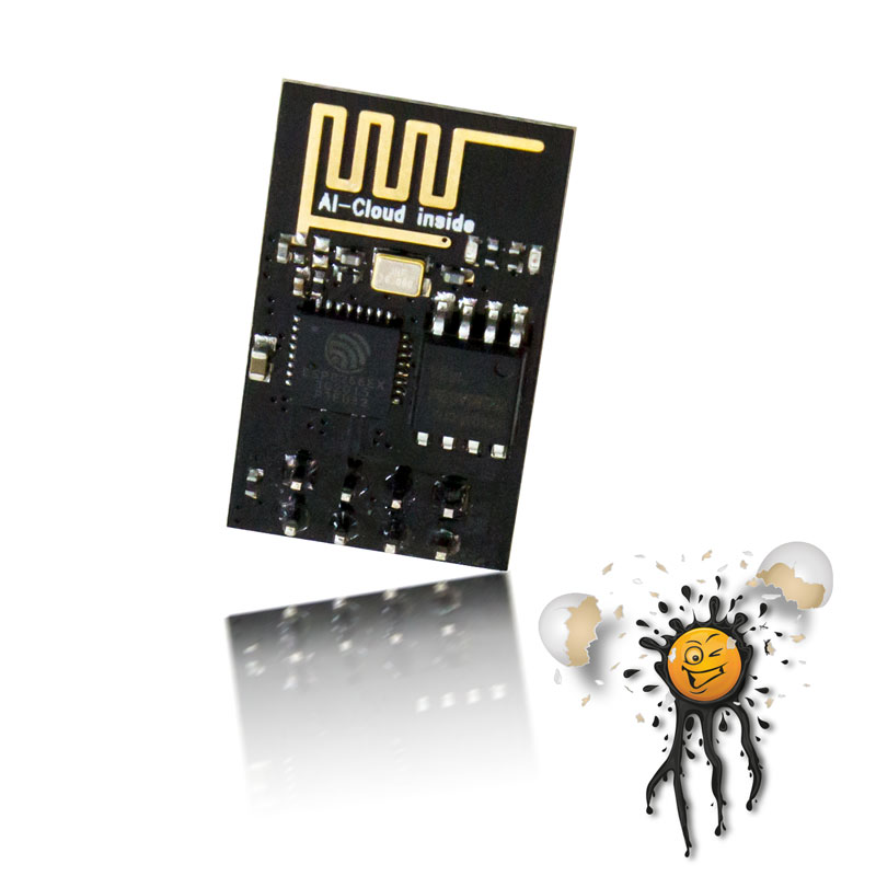
AI Thinker ESP8266 ESP-01 Tasmota Firmware © androegg
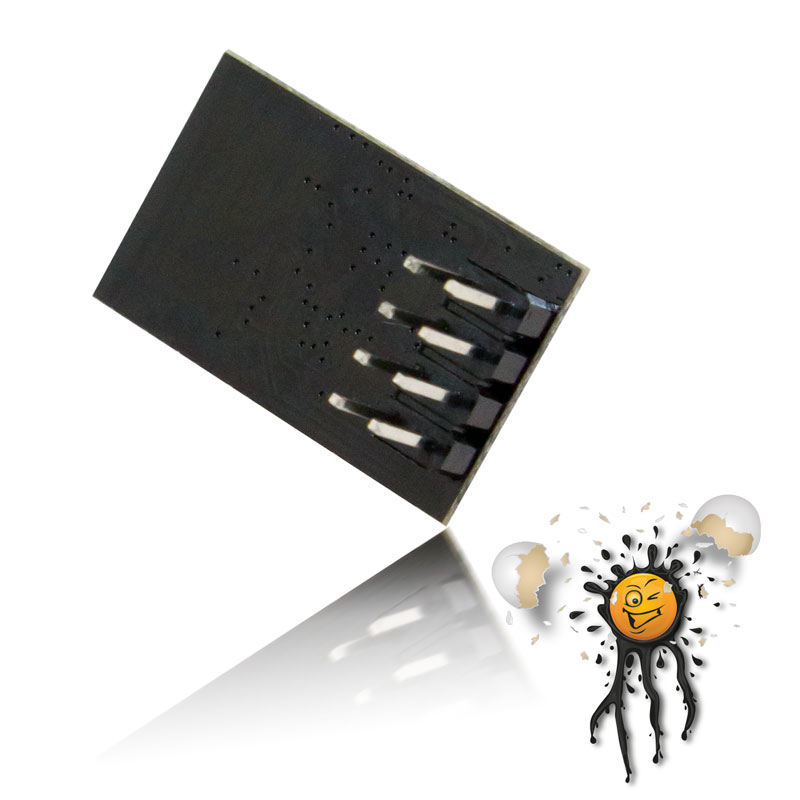
ESP8266 ESP-01 Pins 2.54 mm Pitch © androegg
Tasmota ESP8266 Firmware Web Interface Network Scan © androegg

Smart Home Tasmota Relay WiFi Overview © androegg
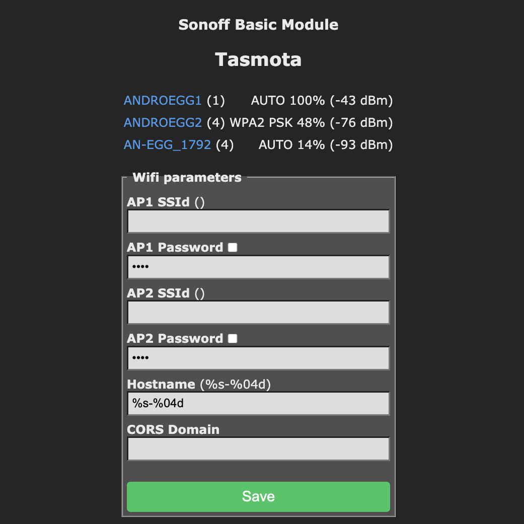
Tasmota ESP8266 Firmware SSID configuration © androegg

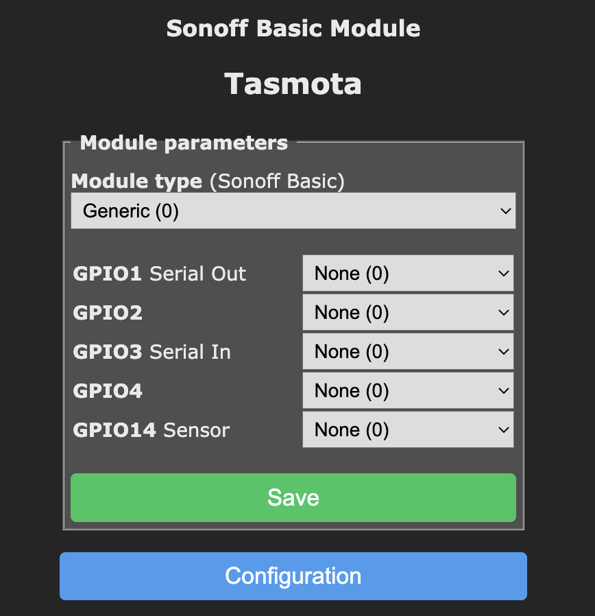
Tasmota Firmware module configuration © androegg
Tasmota Firmware Relays configuration © androegg

Tasmota ESP8266 1CH Firmware template © androegg

|
|
Das ESP8266 ESP-01 1 Kanal Relais Set beinhaltet:
- 1 Stück ESP8266 ESP-01 mit Tasmota Firmware
- 1 Stück ESP-01 1 Kanal Relaismodul
WLan ESP-01 Relais Modul
Das ESP-01 1 Kanal Relais Set erlaubt die einfache Anbindung mittels Webinterface beipielsweise an
- WLan Netzwerk
- MQTT, z.B. Mosquitto, ioBroker, usw.
- Domoticz
- FHEM
- …
Das ESP-01 Tasmota 1 Kanal Relais eignet sich zum
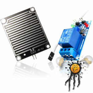
Das ESP-01 1 Kanal Relaimodul verfügt über
- passenden Anschluss für den ESP-01
- Spannungskonverter für eine Versorgungsspannungen von 5V
- Relais Schraubklemme 3-polig
- NC (Normally Closed)
- COM
- NO (Normally Open)
- Schraubklemme 2-polig für 5V Spannungsversorgung
- VCC 5V+
- GND 5V-
Tasmota ESP8266 Firmware
Das ESP8266 ESP-01 1 Kanal Relaismodul verfügt bereits über die Tasmota Firmware (sonoff version) und kann mittels dem integrierten Webinterface in wenigen Schritten konfiguriert werden:
- Wenige Sekunden nach Spannungsversorgung erscheint ein neuer AP (Access Point) TASMOTA_???? in der WLan Netzwerkumgebung
- Die Anmeldung erfolgt unverschlüsselt und ohne Passwort.
- Nach Herstellung einer WLan Netzwerkverbindung wird mittels Browser das Tasmota Konfigurationsmenü unter http://192.168.4.1 aufgerufen
- Zur Anmeldung im lokalen Netzwerk kann
- mittels Klick auf Scan for wifi networks die Liste verfügbarer Netzwerke aufgerufen und durch einen Klick übernommen werden
- alternativ kann das WLan Netzwerk durch Eintrag im Feld AP1 SSId konfiguriert werden
- Des Weiteren muss im Feld AP1 Password das SSId Passwort angegeben werden
- Im Feld Hostname kann ein eindeutiger Hostname (Name des Moduls im Netzwerk) angegeben werden., andernfalls wird der von Tasmota festgelegte Hostname (TASMOTA_?????) übernommen
- Durch Klick auf den Button Save werden die konfigurierten Daten übernommen und im ESP8226 gespeichert.
Das ESP8266 Modul startet neu und meldet sich im konfigurierten WLan Netzwerk an.
- Dabei bezieht das ESP8266 Modul mittels DHCP eine neue IP-Adresse. das heisst, der erneuten Aufruf des Tasmota Webinterface mittels Brwoser erfolgt nun mittels Namensauflösung des zuvor festgelegten Hostname, beispielsweise http://TASMOTA_????? bzw. http://TASMOTA_?????.local
- Sollte eine Namensauflösung nicht unterstützt werden, einfach im Router Webinterface, in der Übersicht verbundener WLan- / Netzwerk- Geräte die IP Adresse des Tasmota Moduls ausfindig machen.
- Schlussendlich muss nun noch das ESP8266 Modul mittels Klick auf den Button Configure Module für das ESP-01 1 Kanal Relais konfiguriert werden.
- im Drop Down Module type den Wert Generic (0) auswählen
- durch Klick auf den Button Save erfolgt ein Neustart des Moduls
Nach erfolgreichem Neustart erneut in die Module Configuration wechseln um das Relais zu konfigurieren. Das Relais wird über GPIO0 geschaltet, diesbezüglich im Auswahlfeld D3 GPIO0 Button1 auf Relay1i (29) setzen und durch klick auf Save speichern.
Nach dem Neustart erscheint nun erscheint das Tasmota Template mit
- Relais Statusanzeige OFF
- dem Button Toggle zum Schalten des Relais
Sollte die WLan Konfiguration fehlerhaft sein, kann die Tasmota Firmware mittels einfachem Hardware Reset (Boot Count) zurückgesetzt werden, hierzu
- das ESP8266 Modul mit 6 mal hintereinander für 1-2 Sekunden mit Spannung versorgen, bei der 7 Spannungsversorgung erscheint erneut der TASMOTA_???? AP
|
The ESP8266 ESP-01 1 Channel Relais Set is incl.
- 1 pcs. ESP8266 ESP-01 Tasmota Firmware
- 1pcs. ESP-01 1 Channel Relais Module
WiFi Relais UART Module
The ESP-01 1 Channel Relais Module Set is perfect for easy integration into
- WiFi Network
- MQTT, Mosquitto, ioBroker
- Domoticz
- FHEM
- …
The ESP-01 Tasmota 1 Channel Relais is perfect for
The ESP-01 1 Channel Relais Module features:
- ESP-01 Socket Connector
- Power Converter, supports 5V power supply
- relais screw connector 3-pole
- NC (Normally Closed)
- COM
- NO (Normally Open)
- power supply screw connector 2-pole 5V power supply
- VCC 5V+
- GND 5V-
Tasmota ESP8266 Firmware
The ESP8266 ESP-01 1 Channel Relais Module is based on Tasmota (sonoff version) Firmware. Tasmota Firmware features an integrated web interface for easy configuration.
- after starting ESP8266 Module a new WiFi AP (Access Point) TASMOTA_???? appears
- connect to new TASMOTA_???? AP without password
- after WiFi connection open webinterface at http://192.168.4.1 thru browser
- for client WiFi network configuration
- click on Scan for wifi networks for getting a list of available WiFi Networks and click on name of listed Wifi networks
- or write SSId name in field AP1 SSId
- enter valid SSId password in field AP1 Password
- enter a unique hostname in field Hostname (unique Module name in WiFi network), default Hostname is TASMOTA_???? AP Name above
- click on button Save
The ESP8266 Module restarts and establishes a WiFi Client connection.
- The client connection is based on DHCP, so the modules IP address is set from router. To reconnect to web interface thru brwoser use given Hostname for example http://TASMOTA_???? or http://TASMOTA_???? .local
For getting modules actual IP address
check your router for newly connected devices
- to activate / configure ESP-01 1 Channel Relais Module click on Button Configure Module
- select in Drop Down field Module Type value Generic (0)
- click on save
- Last Step is configure the Relays. The Relays is controlled thru GPIO0, to activate Relays thru Module Configuration set D3 GPIO0 Button1 to Relay1i (29) and click on Save.
The ESP8266 ESP-01 Relays Module restarts, the configured template with
- Relais state OFF
- Relais swicth button Toggle
The ESP8266 Tasmota Module supports hardware / Boot Count based factory default reset. For factory default reset
- connect ESP8266 6 times to for 1-2 seconds to power supply, on seventh restart again TASMOTA_????? will appear.
|