NodeMCU ESP8266 ESP-12F + 0,96 SSD1306 I2C 2-color Display

8,47 

NodeMCU ESP8266 ESP-12F + 0,96 SSD1306 I2C 2-color Display

Lieferzeit: sofort

Beschreibung

NodeMCU ESP8266 ESP-12F + 0,96 SSD1306 I2C 2-color Display Linux Win OS X Entwickler Development Board

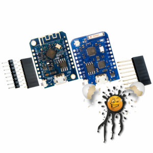
ESP8266 NodeMCU + 2-color 0.96 I2C Display Development Kit © androegg

ESP8266 NodeMCU + 2-color 0.96 I2C Display USB-C Socket © androegg

ESP8266 NodeMCU + 2-color 0.96 I2C Display USB-Micro Socket © androegg

ESP8266 NodeMCU + 2-color 0.96 I2C Display Board CH340 USB TTL Converter © androegg

Das NodeMCU 0.96 Display Board ist wie folgt verfügbar:

  • USB-C Entwicklerboard
  • USB-Micro Entwicklerboard


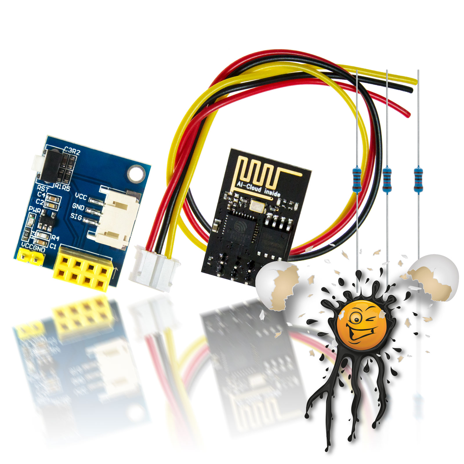
Der Lieferumfang umfasst:

  • 1 Stück NodeMCU 0.96 Display Board
  • 2 Stück Pinleisten


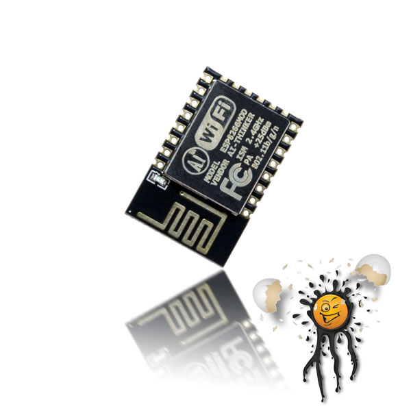
Das NodeMCU Display Entwicklerboard basiert auf dem ESP8266EX von Espressif in Kombination mit dem 0.96 SSD1306 I2C OLED Display.

Ferner verfügt das ESP8266 Display Board über

  • CH340 USB TTL Konverter
  • AMS1117 3.3 Spannungskonverter
  • Reset Taster
  • Flash Taster

Das zweifarbige (gelb / blau) 0.96 Display basiert auf dem SSD1306 I2C Display Treiber und unterstützt eine Vielzahl von IDE’s.

Die I2C Schnittstelle für das Display ist wie folgt an den ESP8266 angebunden:

  • D6 / GPIO12 SCL
  • D5 / GPIO14 SDA


Neben den typischen Schnittstellen wie beispielsweise

  • GPIO
  • UART / RX TX
  • SPI
  • I2C
  • ADC
  • usw.

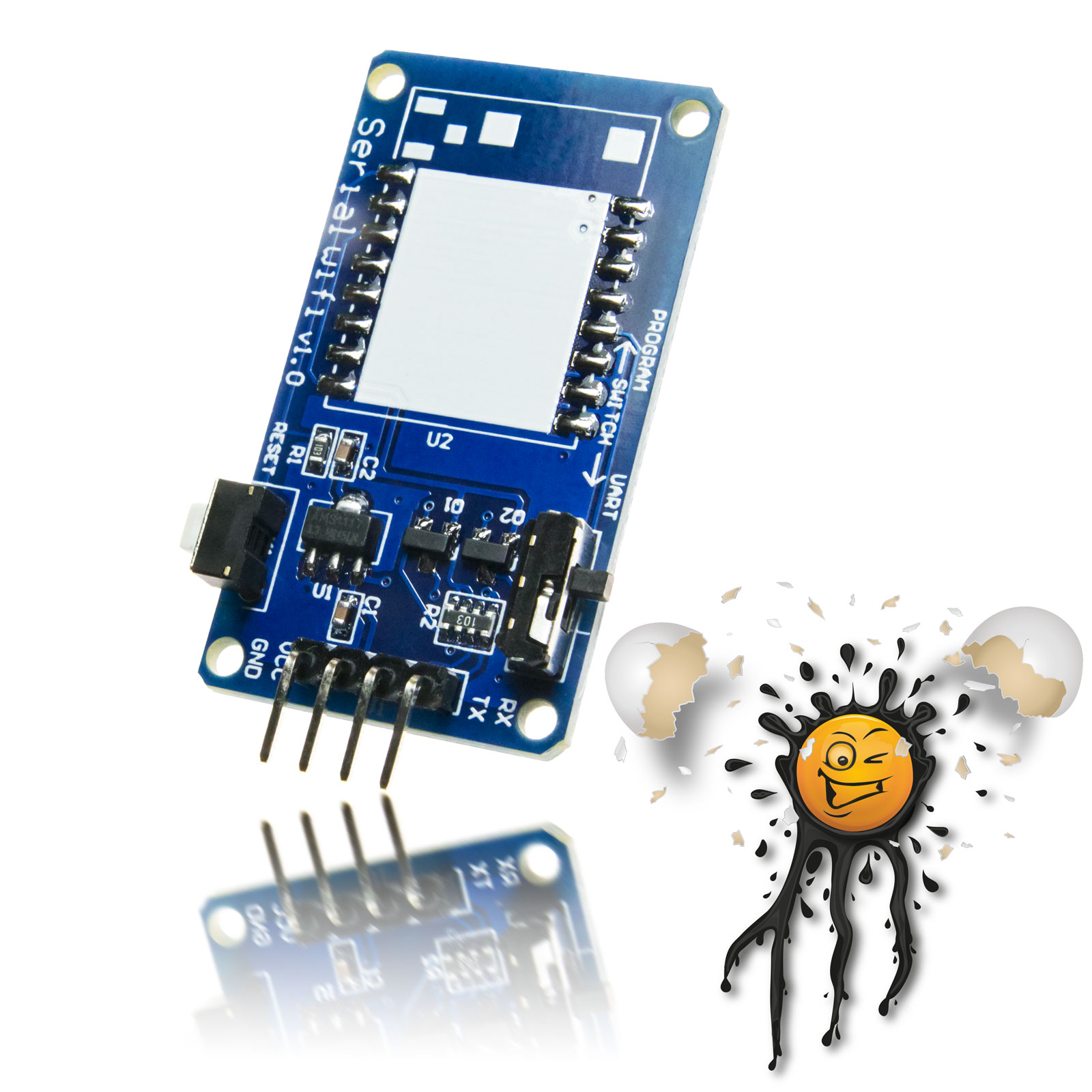
verfügt das NodeMCU Display Entwickler Board über einen integrierten USB TTL / serial Konverter basierend auf dem CH340 um eine direkte serielle Verbindung über USB herzustellen.

Zur Inbetriebnahme muss das NodeMCU Development Board lediglich mit einer freien USB Schnittstelle verbunden werden. Neben der Datenkommunikation erfolgt zusätzlich die Spannungsversorgung über die integrierte Micro USB Schnittstelle.

Im Vergleich zu typischen ESP8266 Modulen erfolgt sowohl der Flash Modus als auch ein erforderliches Reset komfortabel mittels Tastendruck. Ein umständliches Brücken des GPIO0 unter zuhilfenahme von Widerständen ist hier nicht notwendig.

The NodeMCU 0.96 Display Development Board available in 2 Versions

  • USB-C Development Board
  • USB- Micro Development Board


The WeMos NodeMCU Develoment Board incl.

  • 1 pcs. NodeMCU 0.96 Display Board
  • 2 pcs. Pinheader


The NodeMCU ESP8266 Display Board is based on Espressif’s ESP8266EX MCU in Combination with 0.96 SSD1306 OLED Display.

The ESP8266 Display Board has

  • CH340 USB TTL Converter
  • AMS1117 3.3 Voltage Converter
  • Reset Button
  • Flash Button


The 2 color (yellow / blue) 0.96 Display is based on SSD1306 I2C display driver and supports a wide range of IDE’s.

The I2C Interface of the 0.96 Display is connected to

  • D6 / GPIO12 SCL
  • D5 / GPIO14 SDA


Besides typical Interfaces such as

  • GPIO
  • UART / RX TX
  • SPI
  • I2C
  • ADC

the NodeMCU Display Devolpment Board has also an integrated USB TTL / serial Converter, based on CH340 to enable a serial connecteion directly thru USB interface.

Compared to typical ESP8266 Module there is no need connecting GPIO thru resistors to GND for Flashing nor Reset, simply press integrated FLASH or RST Button.


NodeMCU Display Board Features:

  • integrated CH340 USB / TTL Converter
  • integrated 0.96 2-color Display
    • Ilumination: OLED self-luminous display
    • Size: 0.96 inch
    • Color: yellow / blue
    • Working Temperature: -30°C-70°C
    • Module Size: 27 x 17 x 4 mm
    • Viewing angle: 160°
    • Resolution: 128 x 64
    • Interface: I2C
  • integrated 3.3V Voltage Converter
    • supply voltage from 4-9V
  • integrated Reset Button
  • integrated Flash Button
  • CPU / MPU:
    Frequency: 80 / 160 MHz.
    Risk: 32-bit
    Instruction Ram: 64 Kb
    Data Ram: 96 Kb
  • SPI Flash:
    Flash memory: 32Mbit
    clock frequency: 75 MHz.
    Page program: up to 256 bytes in 0.64ms (TYP) Sector erase: 512Kb in 0.6s
    Bulk erase: 17 – 23 s
    Hardware write protection: protected area size defined by nonvolatile bits BP0, BP1, BP2
    Deep power-down: 1μA (TYP)
    Write Cycles: > 100,000 write cycles per sector Data retention: > 20 Years
  • 802.11 b/g/n protocol
  • supports Wi-Fi Direct (P2P)
  • soft-AP Integrated TCP/IP protocol stack
  • integrated PCB Antenna
  • +19.5 dBm output power in 802.11b mode
  • Power down leakage current of < 10uA
  • Integrated low power 32-bit MCU
  • supported Interface
    SDIO 2.0
    SPI
    UART
    STBC
    MIMO
  • A-MPDU & A-MSDU aggregation & 0.4μs guard interval
  • Wake up and transmit packets in < 2ms
  • Standby power consumption of < 1.0mW (DTIM3)

Zusätzliche Informationen

Version

USB-C Board, USB-Micro Board

Tasmota Tutorial

Hier ein einfaches Tutorial zum NodeMCU ESP8266 0,96 SSD1306 I2C Display Modul in Kombination mit einem AM2301.

Das Tutorial beschreibt

  • Flashen der Tasmota Display Firmware
  • I2C GPIO Konfiguration
  • AM2301 Konfiguration
  • SSD1306 Tasmota Console Commands
  • Tasmota Rule zur Ausgabe der AM2301 Sensordaten

Das könnte dir auch gefallen …

Anmelden